Architecture (AR)
Concept:
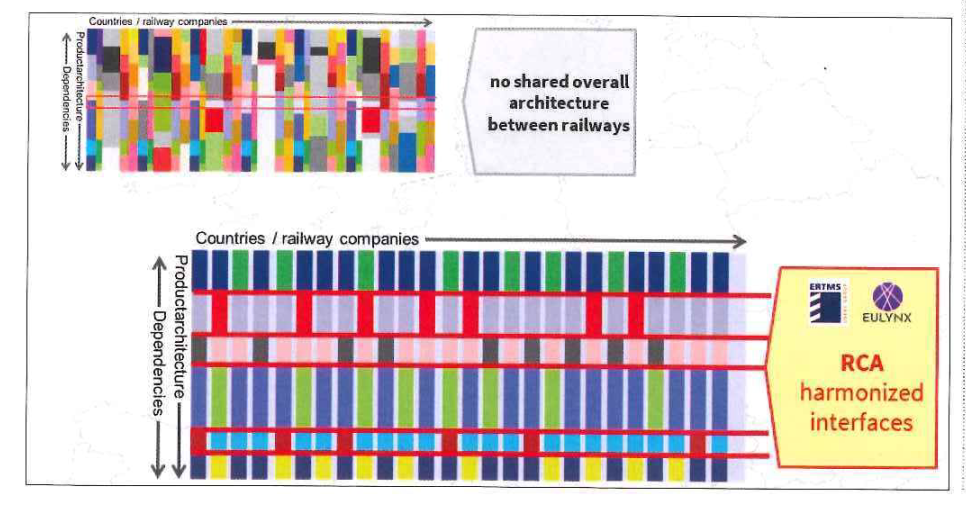
- The current scenario for train control and signalling systems is fragmented. As a result, there is a need to establish a reference architecture that Infrastructure Managers (IM's) can refer to while building their Control Command and Signalling (CCS) systems.
- This will be achieved by evolving existing CCS solutions by:
- Introducing standardized future-proof interfaces such as ETCS and EULYNX, that facilitate modularity, migratibility and adaptability.
- Inclusion of 'Game-changers' namely ATO, train-borne localization, etc.
Scope of the cluster:
- The cluster aims to define the reference architecture in terms of its systems, interfaces, function apportionment, and non-functional requirements.
- The architecture shall be derived from RCA Goals in a comprehensible and traceable way. Main structure for this is provided by a layered model.
- The reference architecture will result in a model and a set of concept and specification documents.
- The architecture should account for the following:
- The architecture shall be derived from RCA Goals in a comprehensible and traceable way.
- Although the reference architecture depicts a target architecture it should also be able to support stepwise migration.
- Prevent functional diversity - every function is designed only once- More diversity means more complexity and more costs. This ensures alignment and functioning interaction of the concerned systems.
- Reduction of trackside assets. Leads to reduction of LC costs and increases reliability.
- Modularity - components should be exchangeable. Requires interfaces that allow upward and downward compatibility.
- Functions are to be allocated to software which should also have the possibility to be automated.
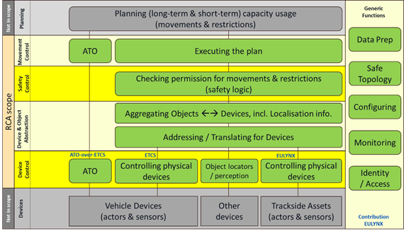
- Below figure depicts the systems involved within the reference architecture with respect to functions separated into layers. The components for these functions are assigned to exactly one layer.
- The functions within these layers are described below:
- Planning (not in scope of RCA): Creating the plan for customers and for production (Operation Plan).
-
Movement Control: These functions implement the operation plan by issuing
single object-control requests (OCRs) when the condition regarding the current operational status are met. These OCRs can, for example, change a switch position or update a movement permission. - Safety Control: These functions check requests from upper layers or users: If they are in a safe state, then they are executed. They also check events and overall status of all objects and invoke emergency reactions for unsafe situations.
- Object Aggregation: These functions combine devices for an abstracted object representation. They co-ordinate devices (actors) for the execution of object-control commands, which should work “hand-in-hand”.
- Device Abstraction: These functions offer abstracted device capabilities (functions and information) and an abstracted device access (e.g., topology-related).
- Device Control: The device-control functions steer and administrate devices. They assure the quality of the de- vice control. They offer easy access to devices via data network for the layer above.
-
Devices (not in scope of RCA): e.g. Train Driver, Field Elements, etc.
- The below figure illustrates the reference architecture showing its main interfaces and subsystems for GoA1/GoA2.
- It depicts the various architecture layers as described above. Each layer consists of one or more systems that interact with each other through interfaces.
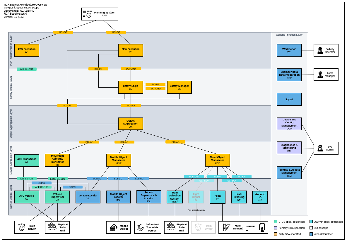
- A more detailed description of various components and interfaces for the above figure are given here:
- Abbreviations:
- SCI: Standard Communication Interface
- SDI: Standard Diagnostic Interface
- SMI: Standard Maintenance Interface
- SAI: Standard Authentication/Authorization Interface
- SWI: Standard Workbench Interface
- SHI: Standard Handover Interface
- AoE: ATO over ETCS
- SS: CCS TSI ETCS Subset
2. Actor Descriptions:
- Railway Operator: The Railway Operator manages, directs and facilitates the movement of trains over an assigned area.
- Asset Manager: The Asset Manager provides all relevant infrastructure data and manages this data.
- Sys Admin: Sys Admin is responsible for the technical operation and maintenance of the RCA systems.
- Field Element: Railway fixed equipment on/or adjacent to track, e.g. light TDS, Point, etc.
- Authorized Trackside Person: Trackside Person is a person working on the construction or maintenance of the trackside infrastructure.
- Mobile Object: An object that is reporting to RCA system but is not able to be controlled directly by RCA, e.g. construction equipment.
- Train Driver: A person capable and authorized to drive trains
- Physical Train Unit: A Physical Train Unit can be a train unit, consist or a vehicle
3. System Descriptions:
- Planning System (PAS): The planning system for the traffic management.
- Plan Execution (PE): PE translates operational plans into discrete requests for movement permissions and state changes of abstract objects representing Field Element.
- ATO Execution (AE): AE translates operational plans into journey profile for automatic train operations.
- Safety Logic (SL): SL grants or rejects requests for state changing of either a Field Element or for a planned movement, based on a safety evaluation.
- Safety Manager (SM): SM monitors the state of the railway operation, recognizes hazardous combinations of states, and triggers safety reactions.
- Object Aggregation (OA): OA routes and aggregates abstract commands to the transactors and aggregates state from into abstract representations of the state of the railway operation.
- ATO Transactor (AT): AT distributes automatic train operation journey profiles, to the on board unit of individual Physical Train Units.
- Movement Authority Transactor (MT): MT translates commands and state feedback between the device-specific track-train message set specified.
- Mobile Object Transactor (MOT): MOT translates between the abstract objects used by the Object Abstraction Layer and the device-specific commands and vice versa.
- Fixed Object Transactor (FOT): FOT translates between the abstract objects used by the Object Abstraction Layer and the device-specific commands from EULYNX subsystems and vice versa.
- ATO Vehicle (AV): AV executes journey profile packet and segment profile packet by controlling the physical functions of the Physical Train Unit.
- Vehicle Supervisor (VS): SubSys VS implements the supervision part of the ETCS on board unit.
- Vehicle Locator (VL): VL uses mobile localization technology to safely and reliably provide position, length and speed information of the train.
- Mobile Object Locator (MOL): MOL provides the position of a trackbound or non-trackbound object on the railway network topology.
- Person Supervisor & Locator (PSL): PSL provides additionally to MOL warnings and protection from approaching movable objects.
- Point (P): P is used to control and monitor the Point machines of movable elements based on a request from the FOT.
- Level Crossing (LC): The LC protects the crossing area of rails and vehicles through its level crossing protection facility.
- Train Detection System (TDS): TDS monitors the vacancy and occupancy status of TVP sections.
- Light Signal (LS): LS transmits information to Train Driver.
- Generic IO (IO): IO is used for integrating signalling systems, controlled and monitored by FOT.
- Workbench (WB): WB is a platform for providing process specific user interfaces.
- Engineering & Data Preparation (EDP): EDP support commissioning and maintenance processes.
- Topo4: Topo4 provides a correct, validated topology and topography data for SIL4 systems.
- Safe Reflexive Reaction Controller (SRRC): SRRC decides if a hazard is caused by an object which is recognized in front of the Train Unit.
- Device and Config Management (DCM): DCM is used to register, setup and manipulate Devices.
- Diagnostic & Monitoring (DM): DM collects monitoring and diagnostics information from subsystems.
- Identity & Access Management (IAM): IAM authenticates and authorizes users and technical systems and grants or denies access to the system.
- Evaluated Train Manager (ETM): ETM registers and monitors multiple Events and relevant data to compute and classify Incidents for the respective Train Unit.
- Evaluated Reaction Manager (ERM): ERM aggregates, maps and monitors multiple Events and relevant data and classifies Incidents with deterministic rules.
- Train Front Monitor (TFM): TFM monitors the defined area by detecting, analysing and classifying specified objects, infrastructure and Events.
- Impact Detection (IMP): IMP detects an impact with an object at the Train Unit Front End and measures the force and location of the impact, for later Incident Reactions.
- Train Interior Monitor (INT): INT monitors the Passenger Crowds in defined areas in a Train Unit.
4. Interface Descriptions:
- SCI-OP: Operational Plan Interface
- SCI-CMD: Command Interface
- SCI-AO: Abstract Object Interface
- SCI-AD: Abstract Device Interface
- SCI-MD: Mobile Device Interface
- SCI-VL: Vehicle Locator Interface
- SCI-PS: Planned State
- SCI-OP: Operational State
- SCI-P: EULYNX SCI-P
- SCI-LC: EULYNX SCI-LC
- SCI-TDS: EULYNX SCI-TDS
- SCI-LS: EULYNX SCI-LS
- SCI-IO: EULYNX SCI-IO
- AoE SS-131: CCS TSI ATO over ETCS SUBSET-131
- AoE SS-126: CCS TSI ATO over ETCS SUBSET-126
- AoE SS-130: CCS TSI ATO over ETCS SUBSET-130
- AoE SS-132: CCS TSI ATO over ETCS SUBSET-132
- ETCS SS-026: CCS TSI ETCS SUBSET-026
- SHI-PE: PE Handover Interface
- SHI-SL: SL Handover Interface
- SHI-SM: SM Handover Interface
- SHI-MOT: MOT Handover Interface
- SHI-MT: MT Handover Interface
- P1: Legacy Interface
- R1 TBD x: Legacy Interface To be defined
Useful Documents/Deliverables:
Deliverables from RCA Gamma:
- RCA Architecture Poster
- RCA Concept: Architectural Approach and Systems of Systems Perspective
- RCA Concept: Informal Architecture Overview